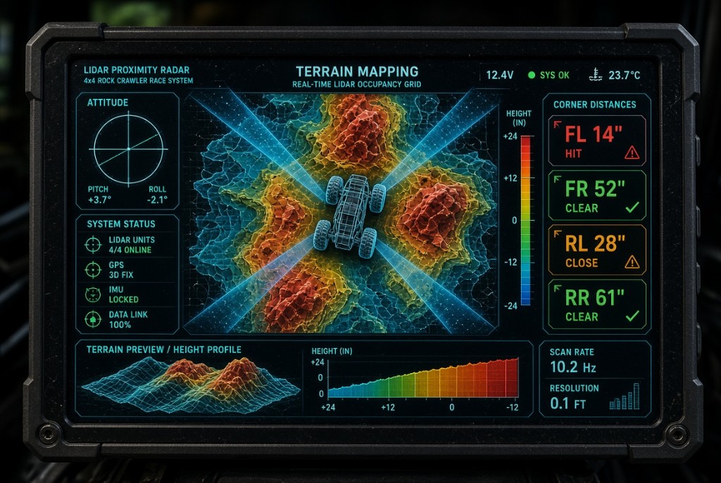
What each block is
- Center grid. About 8 meters on a side. Blue is low ground, red is a rock or a trunk standing up. The truck stays in the middle. The grid is rebuilt every scan.
- Corner distances. Inches from the body to the nearest return in that quadrant, between the rocker and about a meter up. Under 18 inches is HIT. 18 to 36 is CLOSE. Beyond 36 is CLEAR.
- Attitude. Cab pitch and roll from a sensor bolted to the cab, so it matches the seat, not the lidar bracket.
- Bottom trace. A slice of the grid across the truck, so a berm reads as a rise before you put a tire on it.
- 10 Hz and 0.1 ft. The lidars publish about 10 scans a second. 0.1 ft is the grid cell you chose near the truck, not a promise that a rock 30 feet out is measured to a tenth of a foot.
Your board, Rev A
The lidars and the LCD glass are the two things you do not etch. A Mid-360 is a laser scanner, and the Waveshare panel is a finished display. Everything that used to be a pile of bucks, a relay coil, and an IMU breakout is now one board you design: pcb/cab-rev-a.kicad_sch, with the parts in pcb/BOM.csv. Open the schematic in KiCad 8 or 9. The generator that wrote it is pcb/build_schematic.py if you change a value and want the file rebuilt.
Why a Pi 5 is on this board, and the Jetson is not
Binning two clouds into an 8 m grid is a small job. A Pi 5 can do it. A custom carrier for a Jetson module is a couple hundred impedance-controlled pins and a bad first PCB. The Gear tab still lists the Orin Nano if the grid code outgrows the Pi. Rev A does not depend on it. One lidar plugs into the Pi’s Ethernet jack. The other plugs into a USB gigabit adapter until the switch board exists. Both of those jacks can be the rugged ones on your board once that header is wired.
The circuit
- Battery through a 5 A fuse, then an SMBJ24A. That clamp stays under the TPS5450’s 40 V absolute maximum. The FET is an FQD11P06, a −60 V part, so the clamp does not punch the reverse-protection transistor.
- TPS5450, TI’s 5 V example: 10.0 k over 3.16 k, 15 µH, B540A catch diode, 10 nF boot cap, 330 µF on the output. ENA is left open. The chip turns itself on. Solder the PowerPAD or it will overheat.
- J3 pin 3 is 3.3 V from the Pi, into this board. The IMU and the pull-ups run on that pin. There is no second 3.3 V regulator to fight the Pi.
- Ignition drives a PC817. Key on pulls J3 pin 6 low. The HUD treats that as “run.”
- BNO085 with PS0, PS1, and SA0 tied to ground. That is I2C at address 0x4A. Copy the land pattern from CEVA’s drawing. The box in the schematic is the nets, not the pad locations.
Build order
- Install KiCad. Open
pcb/cab-rev-a.kicad_pro. Assign real footprints from the BOM, especially the BNO085 and the TPS5450 exposed pad. - Lay it out as 2 layers, 2 oz if the fab offers it. The loop from PH, through the diode, back to ground, stays under a centimeter. VIN ceramics sit on the pins.
- Order the boards. Before the IMU and the Pi are attached, power it from a current-limited 12 V supply and confirm 5.0 to 5.15 V at J3 pin 1 with a 2 A load.
- Then the Pi, then the IMU. Pitch and roll should move when you tilt the board. Ignition sense should fall when you put 12 V on J2.
- The switch board is next: a KSZ8863 or two USB-Ethernet PHYs, only after this 5 V rail is boring and correct.
Gear
A fixed beam cannot build this picture. Each Livox Mid-360 spins a 3D scan, 360° around and about 59° tall, with its own IMU, over Ethernet. One sits on the cab roof. The other sits on the rear face of the shell and looks back. The shell blocks a roof scanner from seeing behind the truck, so the rear unit is the backup view. The screen is the same Waveshare 7-inch the first build used, so a pod drawn for that panel still fits.
| Part | Qty | Low | High | Job |
|---|---|---|---|---|
| Livox Mid-360 | 2 | $900 | $1,600 | IP67, about 40 m, 9–27 V, Ethernet, IMU inside. Confirm the current price and the vertical field on the datasheet before you order. |
| NVIDIA Jetson Orin Nano Super dev kit | 1 | $249 | $449 | Runs the driver, the grid, and the HUD. A Pi 4 will not keep up with two clouds. |
| Waveshare 7inch HDMI LCD (C) | 1 | $55 | $90 | 1024×600. Module 164.9 × 107.0 × 8 mm. Lit area 154.2 × 85.9 mm. About 300 nit, so the pod still wants a 15 mm hood. |
| BNO085 | 1 | $25 | $40 | Cab pitch and roll. The lidar IMUs ride on the roof brackets and are the wrong attitude for the seat. |
| 12 V to 19 V boost, 6 A | 1 | $40 | $80 | The Orin Nano dev kit wants its 19 V barrel. Do not feed the barrel from raw 12 V. |
| Relay, fuses, primary wire, two outdoor Ethernet runs | 1 | $80 | $150 | Key-on power, and a data cable to each lidar. |
| Roof or rack plates | 2 | $0 | $40 | You make the tilt tabs. |
| Total | $1,349 | $2,449 | About $1,400–$2,500. |
What this leaves out on purpose
- A survey-grade lidar. An Ouster OS0 sees more of the ground in one housing and costs several times this pair.
- GPS as the thing that places the map. At crawl speed it wanders by feet. The grid is stuck to the truck, rebuilt every scan.
- Wheel odometry. That is how a later version remembers the trail behind you. Version one shows what is outside the body right now.
Mount
Two places. The cab roof watches the front and both sides of the cab. The rear face of the shell watches behind the truck. A scanner on the roof cannot see through the shell, so the rear unit is aimed back on purpose, the way a backup camera is.
- Cab roof: center it, near the front edge of the roof, on a rack if you have one. Tilt it about 25° down. A level unit looks at the sky and the horizon. The cable drops inside at the A-pillar, clear of the airbag and the windshield header. This unit fills the screen in front of the truck and beside the doors.
- Rear of the shell: center it on the back door or the rear panel, above the rear window if there is one, lens facing the tail of the truck. Tilt it about 15° down so the scan hits the ground a few feet behind the bumper and still sees a trunk at shell height. A 360° head here spends half its spin looking at the shell. Point the useful face backward and treat the shell side as dead.
- Same brackets work for a cheap practice scanner. An RPLIDAR C1 or LD19 on the cab roof draws the ring around the cab. A TF-Luna, or that same 360° unit with its back against the shell, is the rear view while you learn. Swap in the Mid-360s on these two plates when you want the height colors.
- Keep each lens behind a small aluminum eyebrow so a branch hits the bracket first. Seal the cable hole in the shell with a gland and a drip loop. Run the rear cable inside the shell, then into the cab at the front bulkhead.
- Bolt the BNO085 to a horizontal piece of cab metal, chip parallel to the floor when the truck is on flat concrete.
- The screen stays in the dash. Same radio-stack mount, same airbag rule, same 15° tilt toward the driver.
Wiring on 12 V
The lidars take vehicle 12 V directly. The Jetson does not. One ignition relay feeds both, the way the saved build did: 5 A fuse within 12 inches of the battery positive, relay pins 30 and 87, coil from an add-a-circuit on a key-on fuse in the driver dash. Leave the airbag, ABS, ECU, and fuel-pump fuses alone.
- From the relay output, a 2 A fuse to each lidar on 16 AWG, along the driver frame and up the A-pillar. Drip loop. Each Mid-360 is happy from 9 V to 27 V, so alternator voltage is in range. Still fuse each one.
- Ethernet is the data path. One outdoor Cat6 from each lidar to the Jetson’s Ethernet. A small switch in the dash if you only have one port. Do not run the Ethernet in the same bundle as winch cable. Cross that lead at a right angle.
- A separate 12 V to 19 V, 6 A boost powers the Jetson barrel. Set it with a meter before you plug the kit in. The boost input gets its own 5 A fuse off the same relay.
- The Waveshare panel takes 5 V on its micro-USB, from a small buck on that same switched 12 V, and HDMI from the Jetson. Touch is unused.
- One cab ground stud, scraped to metal. Lidar grounds, boost ground, and buck ground land there.
- Key off kills the lidars at once. Give the Jetson a shutdown before you walk away, or use a supply that holds 19 V for long enough to halt. Pulling 19 V mid-write will corrupt the kit’s storage the same way it corrupted a Pi card.
Software
terrain_hud.py in this folder is the screen. It opens at 1024×600 and draws a synthetic grid so you can see the layout on the Waveshare before either lidar arrives. On the truck, the same draw functions take a real grid.
CRAWL_WINDOW=1 python3 terrain_hud.py
On the Jetson
- Flash JetPack 6 on the Orin Nano Super. That is Ubuntu 22.04. Install ROS 2 Humble and the Livox ROS 2 driver for the Mid-360.
- Give each lidar a static IP on the Ethernet and confirm a point cloud in RViz with one unit on the bench.
- Level each cloud with that unit’s IMU, then throw away points inside the truck’s own body box so the roof and hood are not a rock.
- Bin what remains into an 8 m square, 0.1 ft cells, centered on the truck. Cell value is the height above the local ground. That array is what
draw_hudalready paints. - The four corner inches are the nearest cell in each quadrant whose height is in the body band, from the rocker up to about a meter. Under 18 inches paints HIT. 18 to 36 paints CLOSE.
- Read the BNO085 on the cab for the attitude numbers. Leave the lidar IMUs on the job of leveling the clouds.
The grid is rebuilt every scan and forgotten. The truck is always in the center. Remembering terrain you have already crawled over needs wheel speed or another motion source, and that is a later step, not this screen.