What you are building
The handheld unit in the post sweeps one lidar through a room. On this truck the sensors stay at the four corners of the custom bumpers and look outward, about level with the paint. The number on the screen is inches from that corner to the nearest tree or rock in the beam. Amber means it is inside three feet. Red means it is inside a foot and a half, which is contact range when the lens sits on the widest part of the body.
How a squeeze uses it
- Watch the corner you are steering toward. FL going amber is a tree or a rock inside three feet of the front fender.
- Red on that same corner means the strike is inside 18 inches. If the lens is on the widest paint, that is body contact.
- A rock or a trunk beside the bed lights RL or RR the same way while you pivot or back.
- Pitch and roll stay on the screen so a side-hill is visible without leaving the clearance numbers.
Why these sensors, on a bumper, in the sun
A parking ultrasonic smears a tree trunk into a blob and often cannot see inside a foot. A pencil lidar misses a trunk a few inches off the beam. This build uses a wide-axis outdoor lidar, about 10° or more, with the wide axis horizontal so one beam covers the fender corner and the start of the door. Minimum range around 4 inches (10 cm), UART at 3.3 V, and a face you can hose off. The Benewake TF-Nova class is the current match. Confirm the datasheet in the box for field of view, minimum range, baud, and IP rating before you drill brackets. A TFmini-style 3° sensor leaves a gap a sapling can slip through.
Aim is about 45° out from the bumper and about 5° down, level with the paint. The beam is looking for the thing that will touch the panel, so it stays off the dirt.
What the driver sees
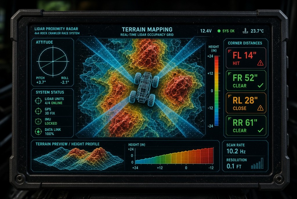
This is the screen crawl_sense.py draws, at the real 1024×600 layout. The sample is a squeeze: a tree 14 inches off the front-left fender, a rock 28 inches off the rear-left bedside, and the other two corners open. Pitch and roll are the cab, not the axles.
The display
Buy the Waveshare 7inch HDMI LCD (C). It is a 7-inch IPS panel, 1024×600, which is the size the program opens. HDMI carries the picture. A micro-USB plug on the same board powers it and would carry touch, which this screen does not use. The Pi stays under the dash. This pod is only the panel.
Waveshare lists the module at 164.9 × 107.0 × 8 mm and the lit area at 154.2 × 85.9 mm. Brightness is about 300 cd/m², so the printed pod wants a short hood or the noon sun on a Tacoma dash will wash it out. Their wiki has a dimension PDF and a STEP file. Use that STEP for the hole coordinates. The drawing below is the outline and the window, so you can start the bezel before the board arrives.
| Feature | Size | Where it comes from |
|---|---|---|
| Panel outline | 164.9 × 107.0 × 8 mm | Waveshare 7inch HDMI LCD (C) specification |
| Lit area, and the bezel window | 154.2 × 85.9 mm | Same specification. Opening smaller than this crops the UI. |
| Pocket in the print | 165.4 × 107.5 × 12 mm | Outline plus 0.5 mm, and depth for the board. Confirm the HDMI shell does not stand proud of 12 mm. |
| Suggested outside of the pod | 196 × 132 mm | About 3 mm walls around the pocket, before the hood. |
| Mounting holes | Use the STEP | Waveshare publishes a 3D drawing. Place heat-set inserts from that file, not from a guess. |
How to print the pod
- Download the STEP from the Waveshare wiki page for the 7inch HDMI LCD (C) and drop it into the model as the thing the pocket has to hold.
- Cut the window to the lit area, 154.2 by 85.9 mm. A lip of the bezel can cover the dead border around that opening. It should not cover pixels.
- Add the 15 mm hood on the top edge. In the truck that edge is up, so the hood blocks the windshield.
- Leave a slot on the port edge for the HDMI plug and the micro-USB power plug, with a drip path so a spill on the dash does not run into the connector.
- Tilt the glass about 15° toward the driver. On a 2000 Tacoma the pod sits on the dash above the radio, bolted to the radio stack or the bezel screws. Keep fasteners out of both airbag covers.
- Print a test frame in draft first and sit the bare panel in it. Then print the pod. PETG or ASA handles a closed cab better than PLA.
The four big numbers are the clearance at each bumper corner. Green is beyond 36 inches, amber is 18 to 36, red is under 18. The traces along the bottom are the last few seconds of that same distance, so you can see a tree closing in before the number goes red.
Parts and cost
Prices are typical US hobby prices in late 2026, before tax and shipping. The lidar and the screen brightness are most of the swing. If a TF-Nova is out of stock, buy the part that meets the rule in the table note, and keep the wide axis horizontal so it covers the fender and the door. The cab screen and the pod dimensions are on the Screen tab.
| Part | Qty | Low | High | Why this one |
|---|---|---|---|---|
| Raspberry Pi 4, 2 GB | 1 | $45 | $55 | Runs the screen. A Pi 5 works if the 5 V supply is honestly 5 A. |
| 32 GB A1 microSD | 1 | $8 | $12 | Boot card. |
| Waveshare 7inch HDMI LCD (C), 1024×600 | 1 | $55 | $90 | The panel the screen layout is drawn for. 164.9 × 107 × 8 mm. It is about 300 nit, so the printed dash pod needs a short sun hood. |
| Short HDMI cable | 1 | $6 | $12 | Keep it under 2 ft so it stays behind the dash. |
| Pi UPS HAT with power-loss shutdown | 1 | $28 | $45 | Key-off has to shut the Pi down cleanly or the card will corrupt. |
| Wide-FOV outdoor lidar, TF-Nova class | 4 | $160 | $280 | UART, 3.3 V logic, ≤20 cm minimum, wide axis ≥10° and mounted horizontal, outdoor rated. |
| MPU6050 breakout | 1 | $4 | $8 | Pitch and roll. Bolt it to the cab, level when the truck is level. |
| 12 V to 5 V buck, 5 A, adjustable | 1 | $22 | $40 | Pololu D24V50F5 class. Set 5.1 V at the Pi under load. Skip LM2596 modules. |
| 12 V to 5 V buck, 2 A, for bumper pods | 2 | $16 | $28 | One in each bumper. Sensors must be powered at the bumper, over a long 5 V run they sag. |
| Automotive relay and socket, with diode | 1 | $10 | $16 | Key-on switch for the whole system. A 20–40 A relay is fine; the load is a few amps. |
| Add-a-circuit fuse tap, mini or low-profile to match the truck | 1 | $7 | $12 | Coil power only, from an ignition fuse. 2000 Tacoma interior fuses are the small blade type in the driver dash. |
| Inline ATO holder, 5 A, plus two 2 A and one 3 A | 1 | $12 | $20 | 5 A at the battery. Branch fuses in the cab. |
| 16 AWG duplex primary wire, 50 ft | 1 | $28 | $45 | 12 V and ground to both bumpers. |
| Shielded 3-conductor 22 AWG, 75 ft | 1 | $35 | $60 | TX, RX, signal ground. One run per bumper, two sensors each. |
| 6-pin waterproof connector pair | 2 | $20 | $32 | SP13 or GX16 is easy to buy. Deutsch DT is the tougher upgrade. |
| USB-UART dongle, CP2102 or FTDI, 3.3 V capable | 4 | $16 | $32 | One per sensor, living in the cab. Jumper each one to 3.3 V. |
| IP67 box, about 4×3×2 in | 2 | $20 | $32 | Buck and splices live here, up inside the bumper, off the leading edge. |
| Cable glands, PG7 | 8 | $8 | $16 | Two sensors, one power, one signal, per pod. |
| Passive piezo and 2N2222 | 1 | $4 | $8 | Optional beep. The screen color is the alert either way. |
| Dash mount that bolts to the radio stack | 1 | $18 | $40 | Keep screws out of the airbag covers. |
| Loom, zip ties, heat shrink, rings, dielectric grease, Loctite 243 | 1 | $20 | $35 | The trail consumes the cheap version of each of these. |
| 1/8 in steel or 3/16 in aluminum for four tabs | 1 | $0 | $25 | You are making the mounts. Scrap is fine. |
| Total | $542 | $943 | About $550–$950. |
Hardware you already need in the shop
- Multimeter, and the habit of checking you are on volts before the probes go in.
- Crimpers for insulated terminals, a stripper, a heat gun.
- Drill, step bit, 1/4-20 tap if you thread the bumper instead of using nuts.
- Eight 1/4-20 × 3/4 in stainless bolts, eight nylock nuts, four 1/4-20 × 1/2 in pivot bolts, fender washers.
- A phone with an inclinometer, or a digital angle gauge.
- A laptop to write the SD card.
- Trim tools for the driver dash and the radio bezel.
Leave these on the shelf
- HC-SR04 and JSN-SR04T ultrasonics. Fine for a garage wall, weak on angled rock, and their close range is poor.
- Any lidar whose wide axis is only a few degrees. A sapling a hand’s width off the beam center will never light the screen.
- A 5 V logic USB-UART with no 3.3 V jumper. Its TX pin will overvolt the sensor.
- An always-hot feed to the Pi with no shutdown. The card dies on the third trailhead.
Mounting on your Tacoma
Toyota’s 2000 brochure lists the stock 4×4 as 66.5 in wide, 10.8 in of clearance (12.0 in on the taller tire), approach about 32°, and departure about 24°. Regular-cab wheelbase is 103.3 in and length with the rear bumper is 183.8 in. Xtracab wheelbase is 121.9 in and length is 202.3 in. There was no factory double cab in 2000. Your lift, tires, and bumpers replace every one of those numbers for aiming. Measure the truck in front of you.
Where each piece goes
- Stand at each corner and find the paint that sticks out farthest: fender flare, bedside, or the bumper itself. The lens goes at that corner, at that height. If the flare is wider than the bumper, put the tab out to the flare or write down how many inches the lens sits inboard of the paint.
- Keep the lens 3/4 in behind the outermost steel. A tree should meet the bumper before the glass.
- Weld or bolt the tab on the corner, yawed about 45° out from straight ahead on the front and 45° out from straight back on the rear. Leave the fairlead and the winch line alone.
- Put the waterproof box high inside the bumper, above the usual waterline of a puddle. Sensor pigtails stay short, about a foot. The long cable leaves the box, with a drip loop, and runs along the frame.
- Front cable: driver-side frame rail, clear of the steering shaft, the exhaust, and any winch lead. Up the firewall through an unused rubber plug, high and clear of the brake booster. Gland it. Seal with butyl. Drip loop on the engine side so water does not run into the cab.
- Rear cable: inside the driver frame rail, zip-tied to existing holes. Do not tie it to the brake line or the fuel line. Come into the cab through an unused floor or cab-wall plug behind the seat, again with a drip loop, then forward under the sill trim to the dash.
- Screen: bolt a bracket to the radio stack or the existing radio-bezel screws, angled at the driver. The 2000 has a driver airbag and a passenger airbag. Keep fasteners out of both covers and out of the column shroud. A 7 inch panel will not fit in the cluster. Above the radio, tilted, is the spot that leaves the speedometer readable.
- Pi and the four USB-UART dongles: low in the dash, where cab air can reach them, away from the heater duct and the windshield sun. The IMU screws to a horizontal piece of cab sheet metal, connector pointing so you can still unplug it, chip parallel to the floor when the truck is on flat concrete.
Bracket
Aim calculator
Start at 45° out and 5° down. The picture is the front-left corner, looking down on the bumper. Forward is up. The dot is where a strike 36 inches along the beam would sit.
Measure sheet
Fill this in on the truck before you order cable. Print the page if you want it on a clipboard.
| Mark | What | Yours |
|---|---|---|
| A | Lens height, matched to the fender lip or bedside | |
| B | Setback behind the outermost steel (start at 0.75 in) | |
| C | Yaw outward after the walk-around (start at 45°) | |
| D | Pitch down after the walk-around (start at 5°) | |
| E | How far the lens sits inboard of the widest paint | |
| F | Cable length, each pod to the dash, plus 3 ft of service loop | |
| G | Wheelbase, so you know which cab you are dressing the harness for | |
| H | Sensor body diameter, for the saddle |
Setting the angle on the truck
- Park on flat concrete. Leave the transmission in park or in gear, parking brake on, chock a tire.
- Stick the phone on top of the sensor. With 0° meaning level, tip the lens down until the phone reads about 5°.
- Sight down the lens, or set a speed square on the bumper face. The beam leaves the corner about 45° out from the centerline of the truck.
- Have someone walk a sheet of cardboard along the fender, then along the front of the door, then out from the corner the way a trunk would stand. That corner’s number should fall. The opposite corner should stay long.
- If the door never moves the number, yaw the lens farther out. If a sheet straight off the corner never moves it, yaw the lens back toward straight ahead. Loctite the pivot after all four corners pass.
Wiring on 12 V
The lidars and the screen track the key. The Pi is on the same switched 12 V, through a UPS HAT that sees the input fall and finishes a shutdown. Follow the HAT manual for its two sense wires. The rest of this section is the truck side, which is the same no matter which HAT you buy.
Relay pins
Use a socketed ISO mini relay with the diode already in the socket, and match the socket’s + mark to the ignition side of the coil.
| Pin | Lands on |
|---|---|
| 30 | Battery, after the 5 A fuse that sits within 12 inches of the positive post |
| 87 | Cab distribution stud |
| 86 | Add-a-circuit on an ignition fuse, through that tap’s 1 A fuse |
| 85 | Clean ground |
| 87a | Leave empty |
What to tap on this truck
The interior fuse panel is on the driver’s side of the dash. Pull a fuse that is dead with the key out and live with the key in ON. Radio, cigar lighter, or an ignition-marked cavity is the usual coil source. Put the original fuse back in the add-a-circuit’s lower slot and a 1 A fuse in the new slot. Some taps are polarized: if the new slot is dead and the original circuit died too, flip the tap. Leave the airbag, ABS, ECU, and fuel-pump fuses alone. The 5 A main fuse is a new holder at the battery. It does not replace anything in Toyota’s boxes.
Ground
One cab ground stud, scraped to metal, star washer, dielectric grease over the joint after it is tight. The buck ground, the Pi supply ground, the USB-UART grounds, and the IMU ground all land there. Bumper grounds return on the black power wire to that same stud. Tie the signal-cable shield to ground at the cab end only.
Connector at each pod
| Pin | Front pod | Rear pod | Color you assign |
|---|---|---|---|
| 1 | Switched 12 V | Switched 12 V | Red |
| 2 | Ground | Ground | Black |
| 3 | FL TX, data out of the sensor | RL TX | Yellow |
| 4 | FL RX, data into the sensor | RL RX | Green |
| 5 | FR TX | RR TX | White |
| 6 | FR RX | RR RX | Blue |
Write the colors on the pod lid. Sensor pigtail colors from the factory vary by batch. The sheet in the box wins. A common Benewake lead is red +5 V, black ground, green TX, white RX. Prove TX before you believe the color: with only power and ground connected, the streaming wire is TX.
USB-UART
- Move the dongle’s VCC jumper to 3.3 V before it touches a sensor wire.
- Dongle RX goes to sensor TX. Dongle TX goes to sensor RX. Dongle ground goes to the black wire.
- Leave the dongle’s 5 V and 3.3 V pins empty. The sensor’s 5 V comes from the pod buck. Back-powering a lidar from a USB dongle over 15 feet of 22 AWG is how you get nonsense ranges.
- Tape FL, FR, RL, RR on the dongles before they go into the Pi. Port order on the Pi will still move; the software section uses stable names.
Noise from the rest of the bumper
A winch lead and a light-bar lead belong on the opposite side of the bumper from the signal cable. Where they have to cross, cross at a right angle and keep going. Do not spiral the UART cable around winch cable.
| Point | Key off | Key on, engine off |
|---|---|---|
| Both sides of the 5 A fuse | About 12.6 V | About 12.6 V |
| Relay pin 87 | 0 V | About 12.6 V |
| Each pod buck input | 0 V | About 12 V, a little less is fine |
| Each lidar red to black | 0 V | 5.0 to 5.2 V |
| Pi buck, measured at the HAT input with the Pi running | 0 V after shutdown | 5.1 V |
Set the pod bucks with a meter before the lidar plugs in. A module that wakes up at 12 V on the “5 V” screw will kill four sensors in one key cycle. Confirm the relay drops out with the key. Then connect one lidar, watch its current if you can, and only then connect the other three.
Software
The display program is crawl_sense.py in this same folder, next to config.json and crawl-sense.service. Copy those three onto the Pi. The Pi runs Raspberry Pi OS Lite, 64-bit, and draws straight to the screen.
What you install
- Raspberry Pi Imager on your laptop, to write the card.
- Raspberry Pi OS Lite (64-bit, Bookworm).
- On the Pi:
python3-pygame,python3-serial,python3-smbus2. All three are apt packages. No extra package index. - I2C turned on for the MPU6050. Serial USB needs no overlay; the dongles show up as their own devices.
Image the card
- In Raspberry Pi Imager, choose Lite 64-bit, set a username, and set a Wi-Fi network you have at the bench. The truck does not need Wi-Fi afterward.
- Boot once on the bench with a keyboard. Run
sudo raspi-config. Turn on I2C. Set boot to console autologin. - Install the libraries and put your user in the groups that can see the screen, the USB serial ports, and I2C:
sudo apt update
sudo apt install -y python3-pygame python3-serial python3-smbus2
sudo usermod -aG video,dialout,i2c "$USER"
Log out and back in so the groups apply.
Name the four ports so they survive a reboot
Plug in one dongle at a time and read the stable name.
ls -l /dev/serial/by-id/
Put those paths in config.json. An empty string means that corner draws “no link,” which is what you want while a cable is still on the bench.
{
  "baud": 115200,
  "ports": {
    "FL": "/dev/serial/by-id/usb-your-fl-dongle",
    "FR": "/dev/serial/by-id/usb-your-fr-dongle",
    "RL": "/dev/serial/by-id/usb-your-rl-dongle",
    "RR": "/dev/serial/by-id/usb-your-rr-dongle"
  }
}
Confirm baud against the sheet in the lidar box. Benewake’s usual frame is 9 bytes at 115200: two 0x59 headers, distance in centimeters as a little-endian pair, signal strength as another pair, two more bytes, then a checksum that is the low byte of the sum of the first eight. The program drops any frame whose strength is under 100, so a muddy lens goes to dashes instead of a fake tree.
How a reading becomes a color
The number is inches from that corner’s lens to the nearest return. Mount the lens on the widest paint and the number is clearance to the panel. There is no baseline to set.
- More than 36 inches: green CLEAR.
- 18 to 36 inches: amber CLOSE.
- Under 18 inches: red HIT.
- A stale reading older than 0.6 seconds draws dashes.
Keys on the keyboard you leave in the glove box, or a small USB pad: 1 through 4 mute FL FR RL RR, Q quit. For a window on the bench instead of fullscreen, run it as CRAWL_WINDOW=1 python3 crawl_sense.py.
Prove one sensor before you mount four
python3 - <<'PY'
import serial
s = serial.Serial("/dev/ttyUSB0", 115200, timeout=0.2)
buf = bytearray()
while True:
    buf.extend(s.read(64))
    i = buf.find(b"\x59\x59")
    if i >= 0 and len(buf) >= i + 9:
        f = buf[i:i+9]
        if (sum(f[:8]) & 255) == f[8]:
            cm = f[2] | (f[3] << 8)
            print(cm, "cm", round(cm / 2.54, 1), "in")
        del buf[:i+9]
PY
Wave a hand through the beam. The inches should fall. If the printout is garbage, swap TX and RX once. If it is silent, the dongle is still on 5 V, the baud is wrong, or the sensor has no 5 V from the pod.
IMU
MPU6050 VCC to Pi pin 1 (3.3 V), GND to pin 6, SDA to pin 3, SCL to pin 5. The program wakes the chip and smooths pitch and roll. On a crawling axle the raw accelerometer is noisy; the smoothing is there so the horizon does not flicker. The ranges remain the thing you drive from. If the chip is missing, the screen says so and the ranges still run.
Start with the truck
Edit crawl-sense.service and replace USERNAME with the account from Imager. Then:
mkdir -p ~/crawl-sense
# copy crawl_sense.py, config.json into that folder
sudo cp crawl-sense.service /etc/systemd/system/crawl-sense.service
sudo systemctl daemon-reload
sudo systemctl enable --now crawl-sense.service
The service uses the KMS video driver so there is no desktop to crash. If the screen stays black, the panel’s manual will have a resolution line for the Pi’s video config. Use that line. A 1024×600 panel is what the layout in the program expects.
The constants CLOSE_IN, HIT_IN, and MIN_STRENGTH are at the top of crawl_sense.py. After a dusty weekend, if a clean lens still drops out, lower the strength gate before you change the colors. If a flare or the bedside sticks out past the lens, put that distance in inches under inset_in for that corner in config.json. The screen then shows clearance to the paint.
Build order
Do the bench before any hole in the bumper. A bad 5 V buck is cheap on the bench and expensive after four lidars are wired.
| Block | Hours | Done when |
|---|---|---|
| Image the Pi, install packages | 1 | Console autologin, I2C on |
| One lidar on the bench, sniffer printing inches | 1.5 | Hand in the beam changes the number |
| Four lidars, labels, config.json | 2 | Each corner moves only its own number |
| Full screen and the IMU on the bench | 2 | A hand in one beam turns that corner amber, then red |
| Four brackets and eyebrows | 3 | Tabs bolted to the bumpers, lenses recessed |
| Fuse, relay, both pods, frame runs | 4 | Meter table passes, key-off kills 12 V at the pods |
| Screen bracket, Pi in the dash | 1.5 | Screen readable from the seat, cluster still visible |
| Cardboard walk around all four corners | 1 | Fender, door, and a corner “tree” each trip only their corner |
| First trail with a spotter | 1 | Ten moves where the color matches what the spotter sees |
Weekend one, at the bench
- Write the SD card. Boot. Install the three packages. Enable I2C. Add the groups.
- Set one pod buck on a current-limited 12 V supply. Confirm 5.0–5.2 V with the meter on the output screws and nothing else attached. Power one lidar from those screws.
- Jumper a USB-UART to 3.3 V. Connect ground and the sensor’s TX only. Run the sniffer. Then add RX.
- Repeat until all four dongles have tape labels and
config.jsonhas four/dev/serial/by-id/paths. - Wire the MPU6050 to the Pi header. Run
CRAWL_WINDOW=1 python3 crawl_sense.py. Tilt the Pi and watch the horizon. Walk a hand from a few feet out toward one lens and watch that corner go from green to amber to red. - Cover one lens. That corner should go to dashes within a second, and the other three should stay calm.
Weekend two, on the truck
- Battery negative off until the 5 A holder is crimped and the relay socket is bolted down. Ring terminal on the battery positive, fuse within 12 inches, then relay pin 30.
- Mount the relay low on the driver’s kick area or on the inner fender, socket down so it cannot fill with water. Ground pin 85. Coil from the add-a-circuit.
- Reconnect the battery. Key on: pin 87 is near 12 V. Key off: pin 87 is 0 V. Pull the 1 A coil fuse and confirm the same drop, so a failure in the cab has a way to kill the system.
- Run 16 AWG to both bumpers in split loom, on the driver frame rail, with a 2 A fuse for each run at the cab stud. Drip loops. Glands into the pods. Set both pod bucks to 5.1 V before the sensors are plugged.
- Bolt the brackets on the four bumper corners, yawed about 45° out, lenses at fender or bedside height and recessed behind the steel. Fit the eyebrows. Connect the short pigtails inside the pods and close the lids with a bead of grease on the gasket.
- Pull the shielded cables with the power loom, shield landed only at the cab. Dongles in, Pi buck set to 5.1 V under load, HAT wired per its sheet, screen on the radio-stack bracket.
- Enable the service. Do the cardboard walk on all four corners: along the fender, along the front of the door, and out from the corner. Loctite the pivots.
- Key off. The lidars should go dark immediately. The Pi should shut itself down and stay down. If it reboots when the HAT gives up, the shutdown signal is backward. Fix that before the first trail, because a bouncing reboot corrupts the card.
On the trail
- Creep the first tight line with a spotter outside. Call the corner the screen paints, and have them confirm the tree or rock is on that panel.
- If a door skin touches something while every corner stays green, that spot is in the gap between the front and rear beams. Yaw the nearby lens farther along the side, or plan a slider sensor later.
- If a corner chatters amber on open trail, the beam is clipping the bumper, a flare bolt, or the ground. Raise the pitch toward level, or trim the yaw until the lens sees open air.
- Before a water crossing that will cover the bumper, unplug the pod connectors. An outdoor face survives rain and a hose. It is a bad submarine. Treat a drowned lidar as a replaceable part.
- At the trailhead, key off and wait until the Pi’s activity LED is dark before you walk away.
- Dashes on one corner: unplug that dongle, check
/dev/serial/by-id, and look for 5.1 V at that lidar. A dark TX line with good 5 V is a broken yellow wire or a swapped pair. - A corner that reads HIT with open air beside the truck: the beam is hitting the eyebrow, the bumper wing, or a license-plate bracket. Look down the lens. You should see air beside the panel, not your own steel.
- Both front corners jump when the winch solenoid clicks: the signal cable is bundled with winch power. Separate them.
- Ranges freeze while the truck is running and work on battery alone: the buck is letting alternator spikes through, or a ground is on painted metal. Reseat the cab ground stud and confirm 5.1 V at the Pi while the engine is at a fast idle.
- Horizon drifts on flat ground: the IMU is on a panel that moves, or it is tilted in the mount. Shim it until pitch and roll sit near zero on your level slab.
- The screen is washed out at noon: add a hood of black plastic, about 2 inches deep, on the top and both sides. A brighter panel is the other fix, and it is already the high side of the parts table.
What this leaves for later
A pair of sensors on the sliders would cover the middle of the doors, which is the gap these four corners leave. They use the same pod, the same frame, and two more lines in config.json. Build the corners first, learn that gap with a spotter, and add the sliders only if a door skin is what keeps getting touched.